|
Secondary Mirror Design

- Musings about the secondary mirror size
- With a 110 cm telescope it's possible to have a very comfortable fully illuminated field of view with a
central obstruction smaller than 20% of the diameter, notwithstanding the relative steep f/4 light cone.
To get a feeling for this, let's compute the required secondary mirror size to illuminate fully a significant part of the field of view
provided by a 2" focuser.
- The focal plane of the telescope is designed at 675 mm from the optical axis (see secondary cage page).
With this value, any diagonal sizing tool (e.g. Mel Bartels' diagonal size calculator)
shows that a 200 mm (7.87") minor axis secondary will create a 37 mm (1.45") fully illuminated field at the focal plane.
- This is a lot more than required for visual observations, for which typically 12 mm (0.5") is recommended. But it would be silly to
make a design that doesn't allow for moving the focal point outward to make space for
extra equipment (video, CCD, field derotation unit).
- One of the interesting possibilities of an over-dimensioned secondary is to be able to use a binoviewer without requiring a magnifying barlow element.
By shortening the truss tubes the focal plane of the telescope moves out and makes space for the light path of a binoviewer.
With a typical 110 mm light path for binoviewers and thus the focal point moving out by this distance,
the fully illuminated field becomes rather small (just a couple of mm), but still the whole field inside a 2" focuser will receive more than 90% illumination.
- To account for a small bevel at the mirror edge, the final dimension of the secondary blank has been put at 206 mm minor axis and 291 mm major axis
(8.11" x 11.46"), so that the optical surface of the secondary will be at least the specified 200 mm.
But even with all this over-dimensioning, the central obstruction is less than 19%!
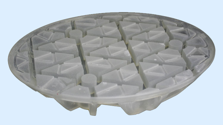
- Reducing the weight by using a cellular design
- A conventional 206 mm (8") full thickness elliptical mirror of this size would be about 45 mm (1.8") thick and weigh an impressive 4.5 kg (10 lbs).
This would annihilate all efforts to make the secondary cage as light as possible.
- A cellular mirror design is a much more exotic and expensive option, but the weight gains are very impressive.
In our case, the weight of a well-designed cellular mirror is only 1.9 kg (4.3 lbs), more than two times lighter than the conventional full mirror.
It's interesting to note that the cellular mirror has an optical surface that is a mere 7 mm (0.28") thick.
- Below some pictures of the cellular mirror blank before polishing. Click for larger versions (pictures courtesy Mike Lockwood).
- The polished secondary mirror
- The surface of the mirror has been fully polished, and is scratch and sleek free and quite smooth. It is very flat along the major axis.
Fringe images show that the over-all accuracy is better than 1/8th wave at 550 nm.
A real beauty!
- Validation of the cellular design by finite-element analysis
- Using a cellular design without validating the structure by finite element analysis is like driving by night with sun glasses.
When 60% to 80% of the material
has been removed, the mirror has a much smaller inherent safety margin than a conventional solid mirror.
- My background in both mechanics and software has been a great help in this phase of the project. To be able to study variations
in the design parameters (support locations, mirror thickness, rib thickness etc) without making very time-consuming and error-prone changes
in the finite element model, I have resorted to writing a computer program MirrorMesh3D that automatically generates the finite element model
of the cellular mirror.
The same automatic mesh generation is also used in the finite element analysis of the primary mirror (more about this later).
Click here to learn more about MirrorMesh3D and how it validates against
David Lewis' mirror cell design program Plop.
- Below an example of such an automatically generated finite element model for the 206 mm secondary mirror.
- In the finite-element analysis several telescope orientations have been modeled: the scope pointing the zenith (upwards), pointing the
horizon, and the 45° intermediate position. An important result is that, with the best support positions, a 40 mm thick mirror
is capable of holding the surface to better than 1/50 wave RMS over the entire surface.
Another important conclusion is that it's best to mount the mirror with the edge of the single support closest to the eyepiece.
- Below a plot showing a typical example of the weight deformation of the secondary mirror (the deflections are exaggerated 500,000 times). The
computations are executed with the open source finite element package Z88.
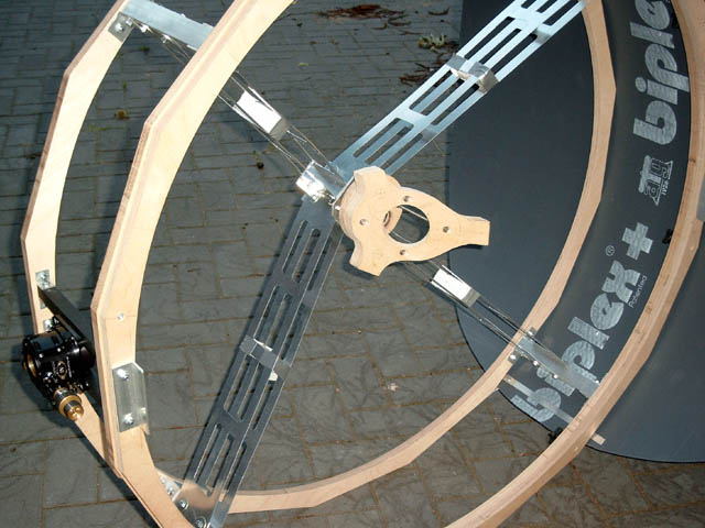
- Secondary mirror holder
- The three mirror support points will be glued to three stainless steel rings using RTV silicone. The steel rings will then be bolted to a
attachment plate that is attached to the center piece of the spider vanes using 4 collimation bolts.
The silicone pads will be flexible enough to take the remaining differential thermal expansion
of the mirror with respect to the attachment plate without deforming the mirror.
- From the conventional construction materials (wood, steel, aluminum), plywood is the best choice for the attachment plate.
An aluminum plate would need to be 9 mm thick to match a 3/4" (18 mm) plywood plate's stiffness and would weigh about the double.
Furthermore plywood's thermal expansion is much closer to glass than aluminum or steel. A carbon plate would be another good choice.
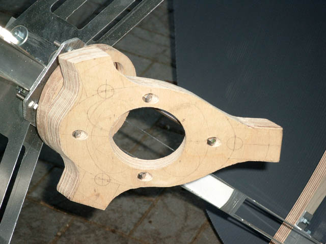
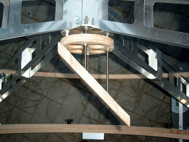
- Below some preliminary images of the mirror holder; I constructed this before doing the finite-element analysis and now know that it's
better to mount the secondary mirror the other way. This means I'll have to make a new attachment plate that switches the support points.
The weight of the spider vanes and secondary holder combined is 1.7 kg (4 lbs), about the same as the secondary mirror itself.
| |


