|
Primary Mirror and Mirror Cell for the 110 cm Cruxis telescope
This page discusses the design of the mirror cell for the cellular primary mirror of the Cruxis telescope.
- Discussion of the cellular 1.1 meter diameter mirror
- The 1100 mm (43.3") primary cellular mirror is 185 mm (7.3") thick and weighs about 125 kg (270 lbs).
The cellular structure contains 108 cells with a half-open back.
The top and back surfaces are 15 mm thick, the internal ribs are 8 mm thick.
Below a view of the back of the mirror in the finite-element model (at the time of writing the mirror blank had not yet been cast).

Note that the cellular design has not been chosen for producing a light-weight mirror. For example Erhard Hänssgen's 42 inch Dobsonian uses a
2.2" (55 mm) thick solid mirror that weighs less than 100 kg.
Producing an ultra-light design was not the primary goal for the Cruxis telescope; optical quality was always the driving force.
The main advantage of the cellular design is the much improved cooling of the mirror.
With a maximum glass thickness of about 15 mm the mirror will reach thermal equilibrium very rapidly - in fact in much less than an hour if
sufficient ventilation is applied.
Notwithstanding the vastly improved cooling properties, the general stiffness of the mirror is much larger than
a much thinner solid mirror. This means that the mirror will be much less sensitive to astigmatism due to thermal issues or
unbalance in the mirror cell.
- Simplified 1100 mmx185 mm solid mirror PLOP analysis
  For reference, a solid 1100x185 mm mirror on a 54-point mirror cell can easily be modeled using PLOP and the following properties:
- Diameter D = 1100 mm
- Focal Length F = 4400 mm
- Edge Thickness = 185 mm
- Central Obstruction = 160 mm (Although the actual size of the central obstruction is 200 mm, it's a good idea to reduce this slightly to take into
account the field diameter)
- PLOP produces the following results for the 54-point cell:
- Visible P-V Deformation: 8.4 nm (lambda/65)
- Visible RMS Deformation: 1.1 nm (lamba/550)
This PLOP analysis gives a very rough idea about the behavior of the cellular mirror.
- The Mirror Edge Support Calculator produces an RMS Surface Error of 3.7 nm
for the cable sling at the center of gravity.
- Finite element analysis of the cellular mirror
- A full finite element analysis of the cellular mirror using Z88 and an automatic generated model by MirrorMesh3D has enabled us to
optimize the surface dimensions, rib lay-out and mirror cell.
- Both the back support and the edge support have to take into account the cellular structure. To prevent distortion of the optical surface the
ribs of the cellular structure have to be loaded evenly. This has been achieved with a 54-point floating point cell, which is basically a
standard 18-point cell in which all the support points are replaced by a flotation triangle, see image to the right.
- For the edge load (the mirror pointing to the horizon) it appears that it is not a good idea to use the thin edge wall for
supporting the mirror. As the edge wall bends the optical surface is distorted on the edge.
Much better results are obtained by putting the load at the level of the top and back surface, where only compression is generated instead
of bending. This has resulted in a double cable sling edge support.
- The finite element analysis produces the following results:
- Vertical mirror weight on 54-point floating point cell:
- Visible P-V Deformation: 11 nm (lambda/50)
- Visible RMS Deformation: 1.8 nm (lamba/300)
- Horizontal mirror weight on double cable sling:
- Visible P-V Deformation: 50 nm (lambda/11)
- Visible RMS Deformation: 8.2 nm (lamba/67)
Both results are quite satisfactory for a 1.1 meter telescope; the mirror cell should not generate any visible error in the mirror surface.
- The whole validation process of the cellular structure has learned us that using cellular mirrors without performing a
detailed finite element analysis is a dangerous way to go.
The thin ribs and walls have a tendency to distort the optical surface if the load isn't sufficiently spread.
Especially the lateral gravity load (edge support) is surprisingly delicate.
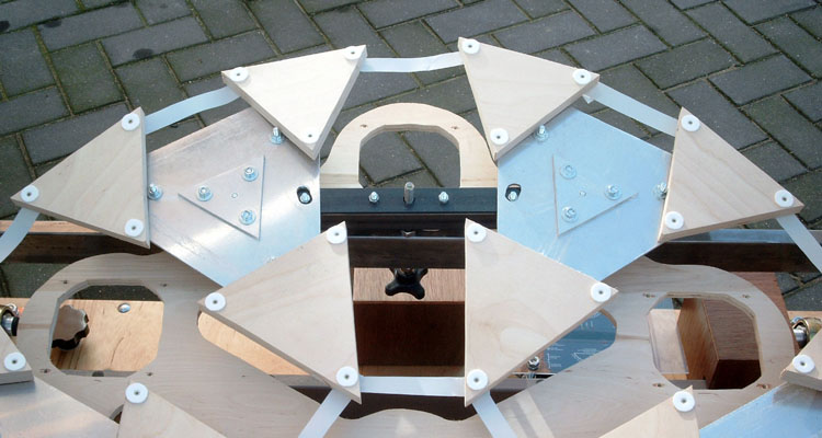
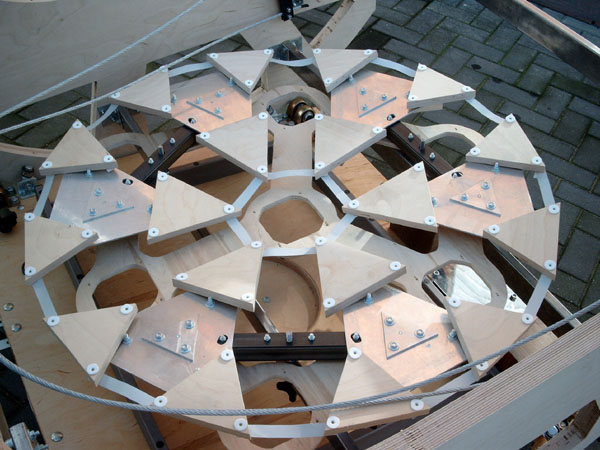
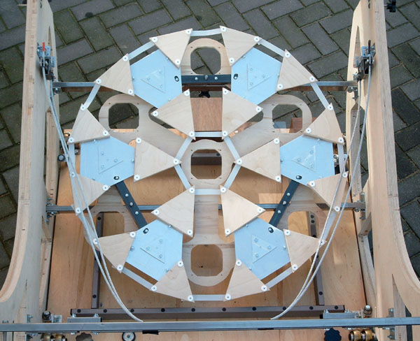
- The 54-point mirror cell
- The mirror cell is in fact a standard 18-point cell in which each support pad is replaced by a triangle. The 18 top level triangles are
made from 18 mm (3/4") plywood, the 6 second level triangles are an aluminum composite structure, and finally the 3 beams that rest on the collimation
bolts are reinforced 30 mm (1.2") square steel tube. The 54 support points are PTFE (teflon) 18 mm diameter and 2 mm thick pads.
The whole mirror cell is a mere 85 mm (3.3") high and is very stiff (computed deflections are less than 0.1 mm).
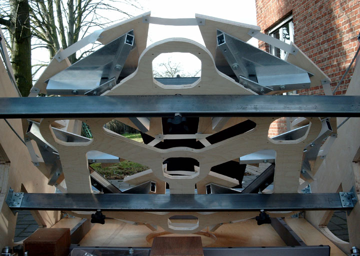
- The pictures show the mirror cell mounted in the mirror box.
Under the mirror cell is the mounting plate for the ventilation system with 7 fans.
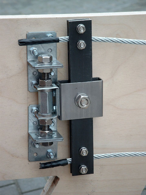
- The double cable sling mirror edge support
- This is an evolution of the standard cable sling in the plane of the COG of the mirror. For the cellular mirror it is better to apply
the edge load near the top surface and the bottom slab. So two cables are used at the bottom and top edge of the mirror.
They're attached to a whiffletree system that ensures that the load is perfectly distributed between the two cables.
The central pivot bolt's height is adjustable and should be put at the level of the COG of the mirror,
so that the resultant force of the edge support is also located at this level.
 The cables are 6 mm diameter steel (6x12 strands) of about 2.5 meter (8 ft) length. One can compute that the 125 kg mirror will stretch the
cables approximately 0.15 mm so that the mirror will move by about 0.075 mm (0.003") between zenith and horizon
(based on a simplified analysis ignoring friction between cable and mirror edge).
The cables are 6 mm diameter steel (6x12 strands) of about 2.5 meter (8 ft) length. One can compute that the 125 kg mirror will stretch the
cables approximately 0.15 mm so that the mirror will move by about 0.075 mm (0.003") between zenith and horizon
(based on a simplified analysis ignoring friction between cable and mirror edge).
- Sag of the mirror cell in the mirror box
- The cell is constructed on two steel beams that are anchored on the side walls of the mirror box (which are also the altitude trunions).
The top beam gets a single support point (collimation bolt) in its center. The bottom beam supports two collimation bolts that are spaced 540 mm apart.
The beams are rectangular steel tubing 60 x 20 x 2 mm weighing about 2.4 kg/meter.
The beams are spaced 468 mm apart.
- Some design data:
- Design weight taken by each support point F = 450 N (45 kg or 100 lbs)
- Length of the beams: L = 1160 mm
- Section modulus of the steel tubing: I = 126,000 mm4
- Elasticity modulus of steel: E = 205,000 N/mm2
- Distance of the support points from the side A = (L - 540) / 2 = 310 mm
- Computation of the deformation of the top beam with one central collimation bolt:
yT = F L3 / 192 EI = 0.142 mm
- Computation of the deformation of the bottom beam with two collimation bolts:
yB = (F A3 / 3 EI) * (1 - 3A/2L) = 0.104 mm
- This shows that the top beam with the single central load deforms more than the bottom beam with the double load off center.
This will tilt the mirror slightly towards the zenith.
The displacement of the focal point can easily be computed:
yF = (yT - yB) / 468 * 4400 = 0.36 mm
- The 0.36 mm displacement of the focal point due to the deformation of the mirror cell nearly compensates the 0.45 mm sag of the
truss tubes that has been computed on the Truss Frame page, producing a mere 0.1 mm (0.004")
resultant sag of the upper cage when moving from zenith to horizon.
- Note that this only works when you put the central collimation bolt on the top beam; if you would put it on the bottom beam,
the two deformations would add up instead of compensating each other.
| |