|
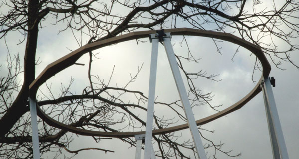
Truss Frame between mirror box and upper cage
 This page discusses the choice of the truss tubes for the Cruxis telescope.
- Lay-out
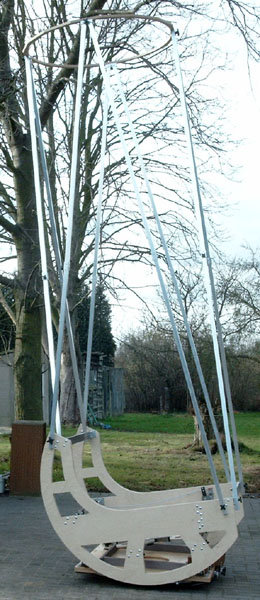
- The truss tubes connect the mirror box to the upper cage. The design of the telescope calls for a truss frame with 8 tubes.
Four tubes are about 3700 mm (12 ft) long and connect to the mirror box at the level
of the primary mirror. The other four tubes connect to the top of the side wall and are about 3200 mm long.
- Tubing material and size
- The stiffness of a truss frame is primarily determined by the elasticity modulus of the material and
the cross-section (i.e. the weight) of the tubes. Steel and aluminum have identical elasticity to weight ratio, whereas carbon tubes will
produce about 2.5 times stiffer truss poles for equal weight.

- Carbon tubes would significantly reduce the weight and provide excellent stiffness, but their cost is prohibitive in the diameter and length that will
be required - probably more than €2000. So classical aluminum tubes will be used for a total cost of around €200.
- A practical limit for the tube weight is about 0.5 kg per running meter.
This would give a total truss frame weight of about (4 * 3.7 m + 4 * 3.2 m) * 0.5 kg/m = 14 kg (30 lbs), or about the same weight as the upper cage.
Using heavier truss tubes would mean that the tubes would mostly be carrying their own weight.
- Several aluminum tube diameter / thickness configurations with weight around 0.5 kg/m are possible:
- round tube diameter 38 mm / thickness 1.5 mm => 0.464 kg/m
- round tube diameter 30 mm / thickness 2 mm => 0.475 kg/m
- square tube side 30 mm / thickness 1.5 mm => 0.462 kg/m
- The three options will give similar performance in a truss frame.
We will use the 30 mm x 1.5 mm square tubing because they're more compact and easier to mount on a flat surface.
The total weight of the truss tubes will then be about 13 kg (28 lbs).
- Transport and assembly of the truss tubes
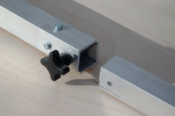
- Square tubes simplify the assembly on a flat surface.
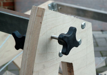
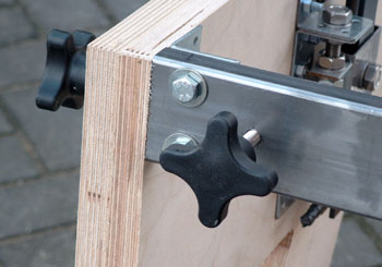
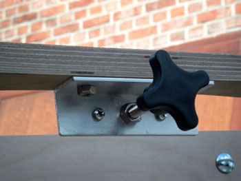
On the mirror box simple stainless steel bolts with ergonomic cross knobs are sufficient to fix the
tubes accurately and firmly.
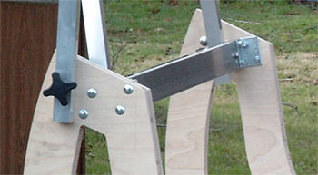 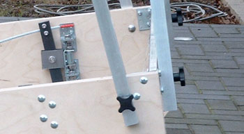
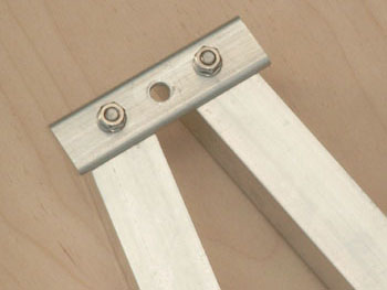
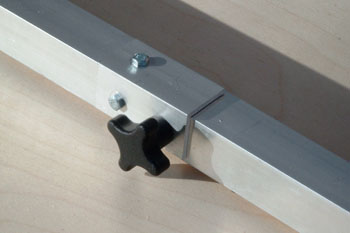
- On the upper cage the tubes are bolted in pairs on a bracket. The tubes remain connected in pairs for easier transport and faster assembly.
- The truss poles have been cut in two for easier transport. The two halves are joined by a sleeve and convenient knob.
- Simplified computation of the sag of the Upper Cage
- The sag of the upper cage of the telescope pointing horizontally can quite easily be computed.
We assume the following design data:
- Design weight: 13 kg (upper cage) + 7 kg (half total tube weight) = 20 kg
- Average free length of the tubes: L = 3350 mm
- Base separation of the tubes: C = 1100 mm
- Cross section of the 30 x 1.5 mm square tube: A = 171 mm2
- Section modulus of the 30 x 1.5 mm square tube: I = 23,200 mm4
- Elasticity modulus of aluminum: E = 70,000 N/mm2
The stiffness of the frame is the combination of the following:
- The tension-compression truss stiffness of the 2 vertical triangles:
ktruss = AE C2 / L3 = 385 N/mm
- The bending stiffness of the 8 tubes anchored at the mirror box and the upper cage:
kbend = 8 * 12 EI / L3 = 4 N/mm
These numbers validate the statement made in the previous paragraph that the bending stiffness is quite small compared to the truss
frame stiffness resulting from axial loads in the vertical triangles.
The total stiffness of the frame is the sum of the two values, approx. 389 N/mm.
With the design load of 20 kg or approx 195 N, the sag would amount to 0.5 mm (0.02 inch) when the telescope is pointing
horizontally. That deflection is quite acceptable and should not harm collimation (the upper cage will not be rotating while sagging).
Furthermore this deflection can largely be compensated by some flexibility of the mirror cell support beams, see the
mirror cell page.
- Finite Element computation of the sag of the Upper Cage and truss tubes
- Using a finite element model of the upper cage and the truss tubes, a more accurate computation can be made that takes into account the
actual lay-out and weight distribution of the truss tubes and upper cage.

- Move the mouse over the image to see the deflections (magnified 100 times).
The computed sag of the upper cage amounts to 0.45 mm (0.018") which compares very well to the result of the simplified analysis above.
The longest truss tubes sag about 2 mm (0.08") in their middle.
- Simplified buckling analysis of the tubes
- It's useful to verify the buckling of the tubes
(consult this site for some theoretical background).
The buckling load for a single truss tube with free ends is:
Pbuckling = 10 EI / L2
In our case the tube is anchored (clamped) at both sides, so we should use a "corrected" length in this formula of
0.65 times the free length of the longest tubes or about 2200 mm.
This yields a buckling load Pbuckling = 3350 N.
The tension/compression force in the 4 vertical truss tubes carrying the weight W = 195 N is:
P = W L / 2 C = 300 N
So there is a comfortable safety margin of about 11 with respect to the buckling load.
| |